And I built a bridge to replace the old one over the pond in my garden.
Eventually, I started on this launch again beginning with the canopy. The canopy will stand on four stainless steel legs when it is up and will form a lid over the cockpit opening when it is down. Being able to raise and lower the canopy has presented a lot of problems which are mainly solved now. At least I now know how to make it all happen but still have to do the work!
I propped the canopy up on temporary short legs in the shed so that I could position the bases for the legs on the side decks and the fittings on the canopy to attach the top of the legs.This is what the temporary legs looked like.
The deck is sloping where the bases land on it and the legs have to be vertical. I shaped some wooden blocks to fit under each leg. The legs will be held firmly in the bases. The fitting at the top is hinged and the reason for this will become clear, read on.
Once the bases were screwed in place (temporarily) I pulled the boat out of the shed for a trial raising of the canopy. Here is the boat with the canopy in its down position.
First stage is to lift the front of the canopy about half way where it is supported on a temporary prop. The aft end of the canopy is sitting on a cross piece of timber so that it can slide for and aft but not tilt to either side as the front is raised.
This is the hard part! The two legs are put in place passing outside the half raised canopy. I stand on the foredeck and lift the canopy to its full height up and over the top of the legs holding it with with one hand while the other hand locates the legs into the hinged fittings inside the canopy.
Standing on the stern deck the canopy is lifted and held with one hand while the other hand puts the legs in the bases and hinged fittings. The canopy is now quite firmly supported but I will add some stays at both ends to stop it blowing away in a breeze!
Lowering the canopy is done by reversing the above process. The whole business of raising with canopy would be much easier with two people. It may turn out that, when the canopy is complete and has solar panels added to it, two people are essential. Time will tell.
The boat has had a temporary floor made out of four pieces of 12mm thick plywood. Three of these run fore and aft; a straight piece down the middle and two shaped pieces on either side. The fourth piece fits behind these. They can be seen in the next photo. I want the floor to have a "planked" appearance similar to the fore and aft decks. I investigated a product called "Top Teak", a synthetic teak looking material and ordered a sample. Here it is:
It looks ok and is a good match to the White Beech decks. It is hard wearing, doesn't stain and has other good features. The manufacturers claim it is less than half the price of a real Teak deck and this is probably correct IF the labout cost is included. My labour is free and the Top Teak material costs at least twice as much as the real timber so I will be using White Beech.
The stern seat is a horse shoe shaped arrangement and I had to make a mock up to get a better idea of proportions and how it would work. The seat has to fit around the motor and its cover. The centre part of the seat needs to be removable to allow access to the batteries that will be under it. The side sections will have lockers underneath.
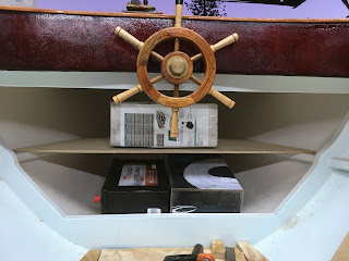
It is hard to make out in the photo but the two black boxes under the seat are mock-ups of 100 Ah 12V batteries. They are a tight fit!
I need 4 of these batteries and the other two will be under the foredeck. Here they are in place, again a tight fit and, given that they weigh about 30kg each putting them in there will be hard work.
While all the above has been going on I have selected a replacement motor and speed controller to replace the noisy motor - click on this link to hear the noisy motor in operation. The replacement motor is about the same size as the noisy one but has more power. The new speed controller is much bigger and is represented by the cardboard box mock-up in the photo above. The new motor and controller come from The Lynch Motor Co in the UK and won't arrive here for quite a while.


No comments:
Post a Comment