This blog describes in words and pictures the building of a Paul Gartside designed fantail launch. There are a number of fantail launches of various sizes on the Paul Gartside website at http://store.gartsideboats.com/collections/steam-launches.

My boat will look like his 20 foot steam launch but will be 18 feet long and will be powered by a small diesel or petrol engine or possibly an electric motor. I have built a rowing boat, one and a half sailing boats and a small canoe and so this will be something different.

If you would like to contact me please click to send me an email.

Monday 28 December 2015

First Layer of Strips Complete

I put the last of the first layer of strips on yesterday. Here are a couple of photos of the bow of the boat. The angle isn't good because I have to stand on a box outside the shed and take the photo through the window. The result is that the photos are foreshortened.


Next job is to clean off the glue and sand the hull "flat" to remove the ridges where the strips didn't quite line up nicely. Also to fill in the small hollows, 2 on each side at the stern and 1 each side at the bow. I could just put strips over the hollows and fill the space with glue but I feel happier with this  two stage process.

Wednesday 23 December 2015

Taking Shape

Reached another small milestone today when I put the last plank, in the first layer, on the stern. It is beginning to take shape and starting to look like a fantail launch. Three photos give some idea of the shape.


From some angles it looks as if there are some hills and hollows that shouldn't be there. I need to check by bending a fairing batten over the hull but the thought of doing that makes me a bit nervous! What do I do about them if they are there?


Thursday 17 December 2015

A Milestone!

Here are a couple of photos showing where the planking is up to. I put the last couple of planks on the stern, starboard side, this morning. Moved the tools round to the port side ready for the next few days work. Remember that the boat is upside down so you have to be careful about which is port and starboard!


Monday 14 December 2015

Fitted Some Planks

A couple of weeks have passed since the last post and progress has been slow. Faced with the need to cut a lot of 100mm wide plywood strips I went looking for a small (tiny) circular saw with a fence. I found one with an 85mm diameter blade made by Worx. Here it is:


The saw part is quite good, light and easy to hold and the blade is narrow so less sawdust. The guide is a piece of crap! The black plastic guide is original, very narrow and difficult to keep against the edge of the sheet of ply. I added a pice of aluminium angle and this was a big improvement and showed up the next flaw - the guide is not parallel to the blade. There is no adjustment so I had to insert shims in various places to get the guide lined up. Now it works reasonably well.

While I was looking for the above I found and bought this device. I already had Ryobi batteries and chargers so the saw wasn't very expensive. It is hardly a boat building tool but it does an amazing job of pruning in the garden. I have a huge hedge to cut down and this saw makes the job so much easier.


Here's the set up for ripping the sheets into strips. The sheet is laid flat on a couple of trestles with a pair of 2x4s to support it. The first strips are easy to cut but the last 2 are a bit fiddly because the 2 clamps have to be moved to allow the saw to pass.


I ripped up 3 sheets of ply into 36 strips; this is probably enough to put one layer over about 2/3 of the hull. The two 2x4s on the bench are a  "vice" to hold the strips vertical so I can plane the edges. One of the 2x4s is clamped to the bench and in use the ply strip is clamped between them.


Fixing the first few planks involved me in a steep learning curve. Each plank has to be fitted to its neighbour that is already in place. To do this it has to be clamped in place leaving a minimal gap and a line drawn on it parallel to the neighbour's edge. It is unclamped and trimmed to the line and then test fitted. It is very important that the plank lies flat on the mould while these steps are being done. If it isn't flat there is a twist in it and it will not fit nicely against the neighbour. Don't ask me how I know this!


I covered the mould with clear 50mm wide packaging tape so the planks would not be glued accidentaly to the frame. Having done that I raided the kitchen and covered the whole thing with cling film. This was a mistake because I had to cut through the film to clamp the planks in place while fitting them. I have removed the film from the areas I am working one.

This next photo shows the planking going on the other side of the boat. The nearest plank with the clamps is being marked along the edge to fit its neighbour; this process is called "spiling".


By this stage I have fitted 6 or 7 planks to both sides of the hull and have established a routine. Clamp, spile, unclamp, trim edge, test fit with clamps, trim if necessary, mix epoxy, prime all surfaces to be glued including the long edges which is a pain, thicken epoxy, apply thickened epoxy to one of all mating surfaces, put plank in place and nail to mould starting at the keel, add a clamp at the gunwale, clean up excess epoxy and make sure the joint between the planks is full of glue. This takes about 45 minutes.

By this stage I am using longer (16mm) plastic nails because the original 12mm ones didn't hold reliably where the curve was pronounced on the bilges. The clamp on the gunwale probably isn't necessary but I have to put it on to hold the plank while I am putting the last few nails in.


Wednesday 2 December 2015

New Tool In The Shed

After a long discussion about what I was proposing to do the Australian agent for Raptor polymer nails, brads and staples suggested that their 12mm (actually 1/2") long 15G nails would do the job. I was a bit sceptical because there would only be 7mm of nail holding the 5mm ply in place. He was confident enough to send me the gun without payment and for me to return it if it didn't work!

Here is the new tool before firing the first nail. It is a nice piece of work made in Italy.


Some testing on the bench showed that I needed to back off the depth control on the gun as far as it would go so that the nails weren't punched almost through the plywood. Once that was done I went back to testing on the boat. The next two photos show a couple of strips in place with the heads still below the surface. In the nearer strip I put in two nails but in the second strip there is only one except at the bottom where I put in two (the first three missed the frame!).


There's a gap between the two strips because they are parallel. When they are fitted finally the second strip   has to be trimmed to fit the one that it buts up against.

At this point I turned down the air pressure at the regulator and found that I can control the depth reasonably well. The heads can be buried a bit on the first two layers of ply because the depressions will get filled with epoxy. In the third layer the depressions would be a pain - they would need filling or the hull would be covered in dimples.

The frame is pine and pretty soft so I wondered what would happen with the second and third layers of ply where the nails will encounter more resistance. More testing with scraps of ply and various air pressure gave me this result. Backing off the air pressure a bit left the heads sticking up a bit above the surface. The photo shows three that went in too far and three that have been sanded back.


I'm happy with this result and can now get on with the last jobs on the frame before I pick up the sheets of ply early next week and start building the hull.

I realised that it is probably best not to build the stringers into the hull at this stage. Putting the fibreglass cloth inside the hull will be more difficult if the stringers are in place already. So I will take them out and put them in a safe place ready to be glued on top of the fibreglass - at least they will fit. Once these stringers are removed I will need to put in a couple more ribbands to support the planking at the bilges.

Last job will be to cover the frame with plastic tape so the hull doesn't get glued to the frame where it shouldn't.

Sunday 29 November 2015

Home Again; Status Update

The last couple of posts didn't give a completely accurate picture of where the build was up to when I went traveling. Before I left I installed a bit more than half of the ribbands (part of the building frame) and laminated the two stringers (part of the finished boat). Here is a photo.


The white longitudinal strips are the ribbands. Below them are the two stringers which had to be laminated in situ, each from three strips. Usual messy job, glue everywhere hence the newspaper (the only thing the Brisbane Courier Mail is useful for!).

That's where I left it for just over 3 months while I travelled to Canada and the UK.

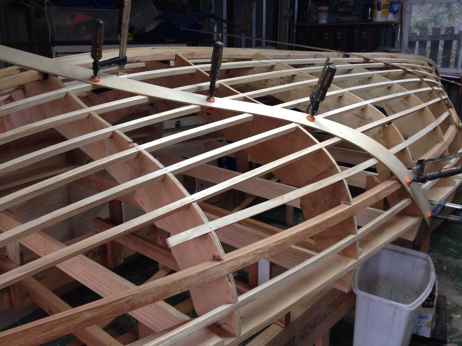
Home again and slowly getting back into boat building. The remaining stringers were added and then the whole thing was carefully "faired" so that a batten bent around the mould in any direction just touched everywhere and lay flat on all the surfaces that the hull lies against. Doesn't sound much but it took a several long hot sessions to complete. Here's what it looks like after that.


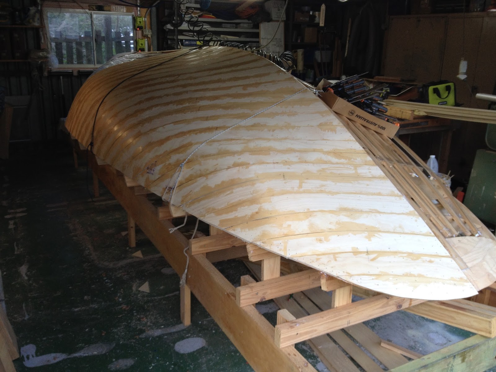
The next stage needed a bit of trial and error to work out what plywood to use and how to fix it in place while the glue sets. The hull of the boat is made up of 3 layers of 5mm thick plywood cut into strips with the strips in each layer laid in a different direction.

What type of plywood to use and how wide can the strips be is the first question. Most plywood is nominally 4mm or 6mm so what I was after was either thick 4mm or thin 6mm, As I looked around I was astonished at the variation in thickness of ply from different manufacturers. Eventually I found a source of Australian mode hoop pine plywood, exterior grade so it has the same glue bond between the plies as the more expensive "marine" ply and with AC face veneers. Not only that it is available in 5mm sheets! After a struggle I bought a sheet to test; it might be manufactured in Brisbane but the retail outlets don't stock it because there is no demand for 5mm ply.

Here are a couple of photos showing the first and second strips in place by clamps with no glue.


The first strip is 75mm wide because I was concerned that a wider strip would be too difficult to bend around the curve down to the gunwale. The second strip is 125mm wide and, while that did take the bend, it was more of a struggle to get it in place. For this part of the hull I will compromise on 100mm wide strips. Towards the ends wider strips will be a possibility. Obviously, the wider the strips the less work is involved but they have to fit nicely to the shape of the boat.

The next question to answer is how to hold them in place while the glue sets. For the first layer clamping is possible but time consuming; on the second and third layers clamps can't be used so an alternative is needed. One technique is to use steel staples through the strips into whatever is underneath. This is OK but all these staples have to be removed, very labour intensive. Plastic staples have been used and these can be left in place - any parts of the staples that stick out are easily sanded away.

I found a source of plastic staples and a staple gun to insert them and went to check it out (far side of Brisbane so a long drive). Looked OK so bought a gun and staples and went home to try them out. Here is the result.


The majority of the staples did not penetrate the plywood. The few that did didn't have enough leg into the timber underneath to hold. Obviously not going to work so another long drive to return the stapler etc and get a refund.

Now I am looking into using either 18G plastic brads or 15G plastic nails. I have been able to try some of the 18G brads and the results are promising but I'm a bit worried about them being able to hold the strips where the curves are pronounced. The 15G nails are thicker and have a bigger head so will hold better. Sadly, a different gun is needed to insert the different sizes and I don't want to buy 2 expensive tools d if I don't have to.

I'm still working on this issue!

Wednesday 5 August 2015

Gone traveling!

There will not be much posted here until I get home in November 2015. That's the plan unless I decide to spend longer in the UK. Stay tuned.

Wednesday 22 July 2015

Adding Padding!

It had to happen sooner or later. I was a bit too enthusiastic putting the bevels on the hairpin at the stern and took off too much, easy to do with a sharp plane! So I had to glue some strips of timber on to replace the missing stuff.

With those bits glued and screwed (same error both sides!) I added the first of the ribbands. These have to be notched into the moulds and, as far as I can see, can be placed anywhere. I think 9 or 10 on each side will be OK so started with one in the middle. It is good to see that it assumes a fair shape when it sits in its notches.

In this photo you can see the bevel on the inner keel. This was hard work! I realised it would be so wanted to do it before adding the ribbands, so that I could get my body in between the frames. If you enlarge the photo (click on it) you can see a hollow in the top of the keel just to the left of my duck. This frightened me (and still does) because I thought the top of the keel should be straight. but what will happen is that the planking fills up the hollow more where the angle it comes in at is closer to flat. At least I think that is what happens, I can see it in my lofting. However, intuition says the hollow should not be there!


Saturday 18 July 2015

Ribbands

At least I think they are ribbands - the fore and aft components of the frame that the planking is made over. Long thin pieces of timber about 16 or 17 mm square and 5.3 metres long, 10 each side of the boat so 20 in total. These are not a part of the finished boat so the choice of timber isn't important. I bought some Radiata Pine boards 184x19 mm and scarph joined them end to end. Then ripped them into 17 mm strips on the table saw, turned them on edge and ran them through again to make them 17 mm square.

Ripping long lengths of timber is an interesting exercise; for starters you need twice the length of the material to operate in. Here are some photos of the setup.

The long view; the roller table is a recent purchase and for this operation is very important. It is possible to hold up and control a narrow piece of timber but the full width board is too heavy and unwieldy to feed in a controlled way.


Here is the saw. The yellow device on the table is a feather board. Again it is a bought one and worth every dollar. I have always struggled with improvised arrangements held in place with clamps. This one has magnets to hold it in place and it really does a good job.

Behind the saw are two roller stands that carry the timber over the space between the saw and the workbench where there is a temporary run way to support the board as it runs through. There is just enough space between the saw blade and the back wall of the shed to accommodate the outgoing timber.


Finally, this is one of the by-products!


Friday 10 July 2015

Inner Keel and Stem - continued

Cleaning up these two large laminations was a time consuming process but the clean up was easier to do at this stage rather than putting it off until the hull is built around them. Then the trial fitting and cutting the long hooked scarph joint that will join them together was complicated by their size. Here are photos showing the pieces in place but only the keel to stern block has been glued.


The aft section of the keel has to be tapered as it approaches the stern. The whole length of it has to be beveled so the planking has an appropriate surface to land on.


Here is the inner part of the stem sitting in place. I was impressed at how well it fitted, matching perfectly with the hairpin and first 2 station moulds. The scarph joint is visible where the clamp is at the top.


A view from the front (taken through the window!). Again, a lot of the stem has to be removed to provide a fair landing for the planking. I could do most of this with the stem on the bench where it would be easier to work on or with it glued in place. The advantage of doing it in place is that progress can be checked continually using a fairing batten, hopefully avoiding the need to glue filler pieces on where too much has been removed.

Saturday 4 July 2015

Stern Block, Inner Keel and Stem

The stern block was too small both fore and aft and vertically so more wood was glued on with epoxy. When the glue set I rough shaped it using a long batten across the frames to check progress. There was about half a wheelie bin of shavings to clean up!


The inner part of the keel has a 100x50 mm cross section and is about 4.5 m long. Half of it is straight and half is curved as it comes up to the stern. Clearly this size timber would not bend so it had to be either cut from solid timber (pieces scarph joined together) or laminated from thinner strips. I chose to laminate it and tried a 100x12.5 piece of hoop pine over the curve; it broke! Ended up with 5 strips of 100x10 each of them with a scarph joint somewhere to get the length needed. Then the biggest gluing job I have ever done, five pieces of timber, 4 glue lines to be primed on both surfaces and then one surface coated with thickened epoxy before being stacked along the top of the moulds. Usual problem with clamps - you never have enough of them!


While that lot of epoxy has a couple of days to harden I made a start on the inside stem. Again there is a curve to negotiate and this time it is sharper. I didn't fancy laminating this (at least 10 strips to get to the 50 mm thickness plus possible soaking or even steaming to get them round the bend) so decided to build it out of 25 mm thick blocks. Once again it needs to be 100 mm wide so four layers of blocks with all the joints staggered. Here is the first layer of 4 blocks being glued up over the plan from the lofting - how can it not fit? You can only just see it, there is kitchen film under the glue joints so it doesn't get stuck to the plan.


 Over the next few days I will be cleaning up the sides of the inner keel and building up the rest of the inner stem. Here is a photo of the inner stem with the last layer glued in place.


Saturday 20 June 2015

Fitting the Hairpin and Adding the Frames

Fitting the hairpin was fairly straightforward. It sits on the cross supports at the camber of the deck and is attached to the hairpin with blocks screwed to its underside and to the cross supports. The support at the stem was a bit fiddly to organise mainly because I hadn't thought it through! The forward end of the hairpin is in the photo below.


At the stern of the boat there is a laminated block glued between the ends of the hairpin. I had been glueing up pieces to make this block over the past week or so. Now it is in place I think it might need another layer adding to it. Most of this block will be cut away to make it conform to the shape of the hull.


With the hairpin in place the ends of the cross supports are trimmed off so they don't interfere with the planking when that begins.

Fitting the frames was straightforward; they stand on top of the hairpin and are attached to it with blocks screwed to it and to the frames. That all went smoothly and I was pleased that a batten along the line of the keel touched all the frames nicely. The three photos below show that the boat is taking shape and beginning to look like a boat!


With the frames in place I am reclaiming some of the space in the shed which was taken up with the stacked frames. Tomorrow's job is to do some more reorganising so that I have more working space and don't need to be continually climbing over things that are lying in the way!

Friday 19 June 2015

Building Frame

With the hairpin finished I could lift up the lofting floor and put it to one side. If needs be it can be reassembled but finding enough space to do that would be difficult. Hopefully it won't be needed or, if it is, only part of it will be needed.

With the floor cleaned the building frame could be put together. Here is the basic ladder frame. I was lucky some months ago to find the 2 Glulam beams (200 x 50 x 6 metres) in the local Bunnings store where they were either surplus to an order or had been returned, either way Bunnings wanted them out of the way and they were cheap! They are like 50mm thick plywood, dead straight and will stay that way forever.


The frame is in the right position and the sides will be shortened so that the shed door will close and to provide space at the back of the shed to walk around. The shed is 6 metres and the boat is 5.48 so it is a tight fit. There is enough space under the sides for me to wriggle under and then sit up. This will be awkward  and hopefully not something that I will have to do very often but it will be possible.

The station positions were marked out putting the stern of the boat so it will almost be touching the tilt-a-door when it is closed. The ends of the side beams were cut off, a string line on the centre line and 100mm below the water line organised and the cross beams at each station fitted. Here it is:


More cross supports are needed to support the hairpin or deck shelf. These supports follow the height of the sheerline and are cut at an angle so that the hairpin sits at the camber of the deck. Each of these supports sits on 2 legs coming up from the station cross beams. Getting them centred, at the right height and level was tricky but a batten laid along the centre line touched them all nicely with no kinks!


Next step is to fix the hairpin to the cross supports so that it can be disconnected when the time to turn the boat over comes in quite a few months. This is one reason that I will need to crawl under the frame.


Thursday 11 June 2015

The Hairpin

Once the frames were finished I started on the first half of the hairpin or shelf which runs along the sheer line of the boat on the inside. The cross section of this timber is 100 x 19 mm and it has to be sawn to shape and made in 4 sections butt joined with blocks on the underside. The timber is marked out from the drawing on the lofting floor using nails laid along the line and then sawn and planed to shape. The 4 sections are laid over the drawing, the shape checked and the joining blocks glued in place with epoxy. Weights were used to apply moderate pressure to the joints. Here it is on the floor, bow in the distance, stern near the camera.

Next day I made the other half using the first half as a pattern to draw the shapes on to the Radiata Pine boards.

The next 2 photos show the pieces that will support the ends of the cockpit coaming. They are not glue in place yet and won't be for a long time!


 Finally a photo showing the whole thing laid out on the grass. It actually looks boat shaped already. From end to end it is about 5.2 metres, there is a semicircular block to be fitted at the stern end which will take the length up to 5.4 metres (18 feet in the old system).

 
The black stripes are overspray from when I painted one of the battens black!

This afternoon I made a pattern in scrap ply to the shape of the inside of the cockpit to use when I come to making the cockpit coaming which has to fit the oval shape in the middle. Again, it will be a long time before I need to use this pattern.

Saturday 6 June 2015

Finished the Lofting

The lofting is finished. Drawing the sections through the stem presented a bit of difficulty because my 2 books on the subject went about it in different ways. The Gougeon book was quite sketchy in its description, my book by Kopanycia was more detailed but presented a more complicated approach which was potentially more accurate. I steered a course between them.

The final step was to draw the true shape of the hairpin or shelf that runs along the sheerline much like an inwale. Because the sheer is curved in the vertical plane its length is greater than it appears in a simple plan view. This hairpin is a substantial piece of timber that has to be sawn to shape so we have to have its true shape. The process of drawing it isn't complicated but is hard to describe and, because it is 6 metres long, I can't take photos of it all. You will just have to read the books or wait for photos showing the hairpin as I make it and fit it into the boat, these will make its name obvious.

With the lofting complete (I think) I have started making the moulds or frames that define the shape of the hull. This is fairly straight forward; the only tricky part is transferring the curved edge of the frame from the floor to the piece of timber. This photo shows the timber laying on top of the drawing - 2 pieces about 200 mm wide but jointed with a screwed on strap.

 
The blank is laying on top of the drawing and obscuring the line that needs to be marked and cut so how to transfer it? It is simple and very accurate. A number of substantial (ie double diameter) flat head nails are laid on their sidesm head s on the line, and tapped into the floor. the blank is laid on top and either walked on or tapped with a hammer. Here is a photo of the nails on the line.


The marks on the back of the blank are faired with a batten, the line cut, cleaned up with a plane and tried against the drawing. The ends and notches are marked and cut. When on ehalf is done it is used to make a mirror image of itself. the two halves are joined with another butt strap and the frame is complete.


There are 11 frames to make and over the last couple of days I have made 5 of them.