This blog describes in words and pictures the building of a Paul Gartside designed fantail launch. There are a number of fantail launches of various sizes on the Paul Gartside website at http://store.gartsideboats.com/collections/steam-launches.

My boat will look like his 20 foot steam launch but will be 18 feet long and will be powered by a small diesel or petrol engine or possibly an electric motor. I have built a rowing boat, one and a half sailing boats and a small canoe and so this will be something different.

If you would like to contact me please click to send me an email.

Friday 23 December 2016

Stern Tube and Steering

A week or so ago I collected the rudder, the rudder bearings and the stern tube from David O'Shea at Speed Propulsion Pty Ltd. David has been very helpful with advice and has done a good job on the parts he supplied. Here is the rudder. He will make up the propeller shaft when I have found a propeller and I am working on this as I write.


I'm debating whether to fix some plywood to the flat steel place and give the rudder and aerofoil section. At low speeds this probably won't make much difference but it might look nicer. Either way I will paint it to match the hull.

The stern tube was put through the oversize hole in the skeg and keel and lined up carefully using temporary supports for a straight steel bar through the tube. With the tube in place the space between it and the woodwork at both ends was packed with thickened epoxy. When this had set unthickened epoxy was poured into the rest of the space around the tube through a funnel until it come up through a riser hole at the highest point of the space.


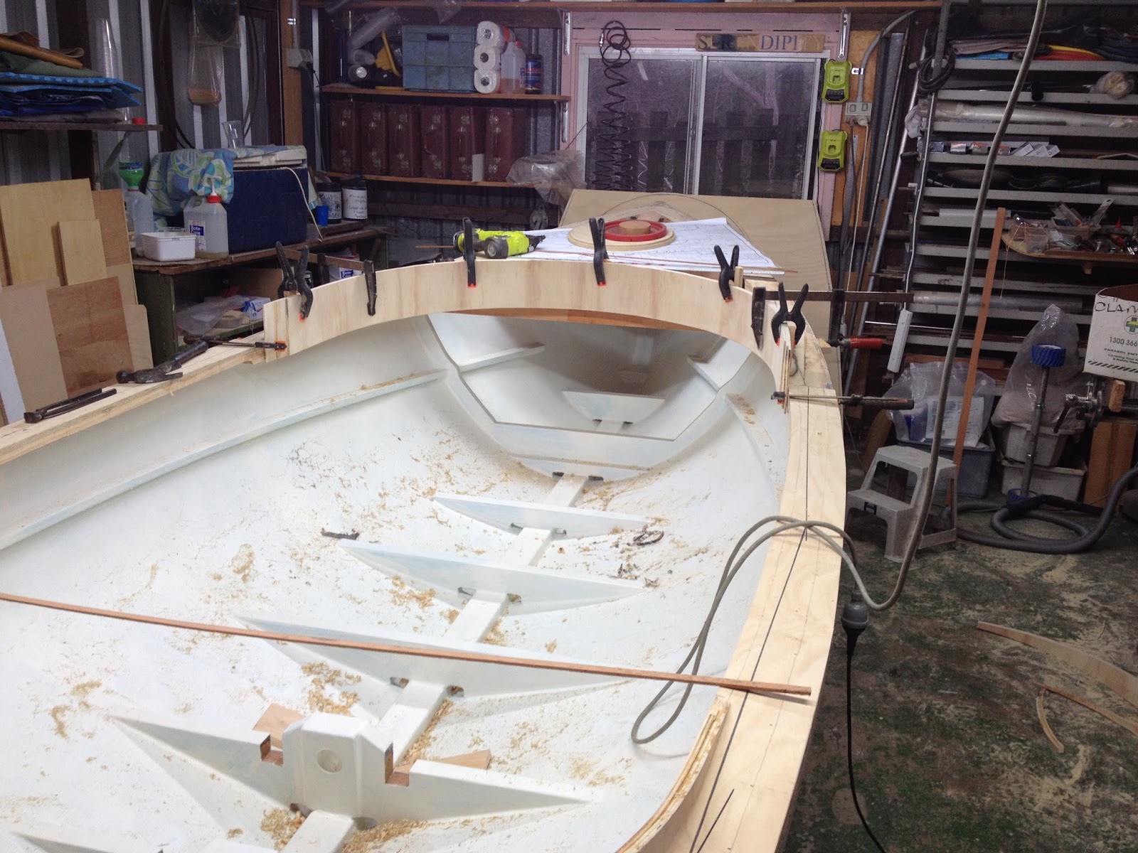
The plan is to use wheel steering with the wheel mounted at the forward end of the cockpit in front of the coaming. I've been making up the parts for this and the arrangement is shown below.


There is a brass axle through nylon bushes in the deck framework. The wheel is at one end and a steering drum is under the foredeck. The steering lines will pass through turning blocks (under the deck shelf) and run under the side decks to a quadrant on the rudder shaft.


The black wheel is just a profile cut from a piece of scrap ply so help me gauge the size of the final wheel. I think the handles need to be slightly longer.

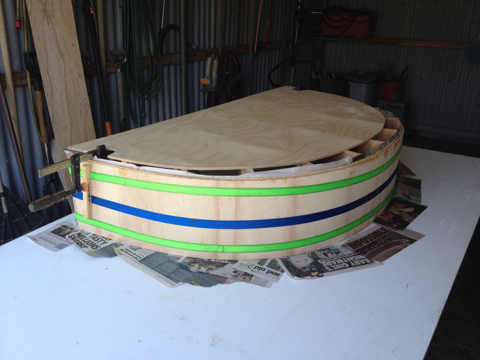
The newspaper was to catch any drips of the walnut wood stain as I applied it to the coaming. There will be a capping strip along the top of the coaming and laminating this will be a challenge!


Cockpit Coaming

Someone mentioned that it is Christmas Day tomorrow - I thought I had noticed some frenzied supermarket shopping and a fat guy with a red outfit! So it seems like a good time for a catch up post or even two!

Because the sheer line rises and the coaming needs to be vertical the laminations needed to be quite wide - I worked out that the forward section needed to be 250mm wide. I made up a light mould for this; it only needs to be light because the bending ply easily takes the shape and the mould only has to withstand the clamping forces. Here are some photos of this process.


The first 2 photos are of the forward coaming clamped up and waiting for the epoxy to go off. The 3rd photo is of the aft coaming ; it is surprisingly stiff now that 3 layers of the bending ply are glued together. The coamings are 15mm thick.

Next step was to glue both coamings in place. A bit tricky holding them in place while clamps were applied. The spring clamps are hold some pieces of scrap timber that sit on the deck to keep the coaming at the right height. The F clamps hold the coaming in place until the glue sets.


With fore and aft coamings in place the 3 laminations of the side sections were laminated in situ. There is a butt joint in each lamination at the end of the side sections and these butt joints are staggered by about 50mm. I didn't like the white timber in the bending ply so I stained the fore and aft sections before I fitted them in place thinking that it would be easier to do the inside face of the coaming below the deck while it was exposed. That was true but.....


With the coaming in place I trimmed to top and bottom edges to follow the sheer line. Then I discovered that I could not match up the stain across the joints in the sections of coaming and also that I didn't really like the cedar colour I had used because it was too red. So it all got sanded off and some darker walnut stain applied.

Friday 25 November 2016

Deck Framing

After the primer and undercoats went on the inside of the hull I started on the framework rhat supports the fore and aft decks. The framework is has a camber across the boat (6mm in 300mm) and follows the sheerline in the fore and aft direction.  Here is a photo of the aft deck.


In the above the top of the framework is all straight: The part with the curve rises in the centre to the high point of the camber, the rest of the pieces are higher than the curved line of the camber and sheer. In the following photos the curved part has been built up by glueing scrap ply on top of it. All of the framework was then faired with a hand plane to provide the camber.


The square hole in the middle of the deck will be a round hole providing access to the steering quadrant. There isn't much room under the deck so the hole needs to be big enough to insert and remove the quadrant from above. The circular coaming is laminated from 2 layers of 5mm thick bending ply.

Bending ply has 2 thick outer veneers and a very thing inner veneer. I don't think the glue is completely waterproof so I will coat the coaming in epoxy.

There will have to be a removable hatch cover and I am still wondering how to make this!


This last photo shows the 6mm ply sub-deck roughly cut to shape and pinned in place temporarily. I took the photo and then took the panels off again! Suddenly the boat looks almost complete but there is a long way to go yet.


I will finish the woodwork under the edges of the opening and then complete the painting of the inside of the boat (including the underside of the ply sub-deck) before I glue the sub-deck in place. Much easier than crawling into the small spaces at the ends of the boat.


Monday 17 October 2016

No More Sanding!

I will probably have to eat the words in the title of this post! All the fillets are in the corners inside the hull. All the fillets have been sanded (actually the surfaces next the fillets have been cleaned up) and the inside of the hull has 2 coats of epoxy.


Next will be primer and undercoat so that at long last the inside of the hull will be a uniform colour. There might even be some finish coats in front of the forward bulkhead while it is still relatively easy to get at.

I have been doing a lot of sorting out of stuff that is simply taking up space, stuff that has been kept because "it might come in useful one day". Two large steel cabinets have moved out of my boat workshop leaving me more useful space. Moving them also gave me access to a corner that hasn't seen the light of day for more than 5 years. Look what I found.


Behind one of the cabinets there was a rat's nest with a long dead resident. At least he/she wasn't preparing to leave the sinking ship before it is even launched!


I had forgotten about this - it has been a long time hiding in the corner. About 10 years ago I was going to build a model steam launch (before I started building large boats and before I moved to Brisbane) and Paul Gartside kindly provided a lines drawing of one of his steam launches. I digitised the lines and then used my small CNC milling machine to make this plug. It's 1 metre long and bears an uncanny resemblance to the bigger version of the Paul Gartside launch that is the subject of this blog. Maybe I will finish the job, cold moulded with some veneer over this plug! Perhaps I should finish the big one first!

Saturday 8 October 2016

Inside Hull Ready To Paint - Well Almost!

This is a status report because 3 weeks have passed since the last post. I've been busy doing other things and there has been little boatbuilding. My aim has been to put in all the fixed woodwork inside the hull and to bring it to a state where I can apply 2 or 3 coats of epoxy and some paint. I wanted to do the finishing work before adding the deck and supporting woodwork, that is to do as much of the painting etc while the inside of the hull is easy to access.

I managed to put in a few hours yesterday and glued in the last two floors. I also shaped the side supports for the forward bulkhead and while doing that realised that I could not glue them in place until the deck beam above the bulkhead was also glued in. So I glued in the deck beam first and then the side supports. Here are a couple of photos showing the floors and bulkhead supports.


In the next photo you can see the "engine" bearers between the last 2 floors and also the steering quadrant on the temporary  (broomstick) rudder shaft.


Here's a close up of the homemade quadrant; laminated plywood with an aluminium bush. The two holes about halfway along the straight sides are where the ends of the steering line will come through to be clamped.


The next photo shows the two aft floors with the engine bearers fitted loosely. When the final drive arrangements are sorted out the bearers will be glued in place. The temporary propellor shaft is in place held in alignment by a couple of wooden bushes in the stern tube hole. The tapered pads on both sides of these floors are where the thrust bearings for the the propellor shaft will be bolted.


I've made a temporary bracket out of scrap plywood to get a feel for how the electric motor will be mounted. The motor runs at too high a speed (about 4000 RPM max) for direct drive and so will need to be geared down. My plan is to do this with a belt drive; small pulley on motor shaft and larger pulley on prop shaft to get down to about 1000 RPM at the prop. The white tin is about the size of the 3kW motor I plan to use. The motor is aprox 180mm diameter and 100mm thick - not very big!


Here is an overhead view, the big pulley (more scrap timber!) is 170mm diameter. When I sort out the final details of the belt drive the height of the motor bracket may be reduced.


Friday 16 September 2016

Floors and Deck Beams

It has been a while since the boat was turned over and in that time I have been filling and sanding the inside of the hull. Waiting for the filler to dry so it can be sanded makes it into a one or two day cycle and because it is also boring I started working on the floors and then the deck beams.

Here is the start of laying out the deck beams. The aluminium box section is 100mm high; its top is at the waterline, its bottom is at the top of the floors. The cross pieces of scrap timber are where the floors will be.


This is how I found the shape of the floors. I could have obtained these profiles from the lofting but this is probably quicker. It isn't my idea, I saw it used in this thread on the Wooden Boat Forum. The pieces of cardboard are stapled to the crosspiece and then this assembly is lifted out and the shape transfered to a piece of scrap plywood.


The plywood should fit but if not can easily be fine tuned. Once the shape is determined it can be transferred to the real timber and cut out with confidence. In the middle sections of the boat where the shape changes slowly the sawn floor should fit. Towards the ends of the boat where the shape changes more quickly the sawn floors need to be bevelled to make a good fit.


In the next photo the two aft floors are in place ready for a pilot hole to be drilled on the centre of the propellor shaft which will pass through them. The drill is fixed in the end of a length of 16mm MS bar with loctite. The bar is long enough to reach through the stern tube hole and is held central in two bushes. The floor to be drilled is held in place by the pavers. Worked like a charm!


With the first pilot hole drilled the floor was removed and two wedge shaped pieces of ply glued either side to provide surfaces at right angles to the prop shaft. These provide the mounting surface for the flange mount bearings that support the inboard end of the propellor shaft. With the first floor complete a 50mm clearance hole was drilled through it. This allowed a pilot hole to be drilled in the second floor. Here are the two floors completed.


The rest of the floors were made and fitted through to the front of the boat. Since then I have been working on the deck beams at both ends. None of the floors or deck beams are glued in place yet but they are more or less ready to be fixed after the inside of the hull has some paint on it. 


While all of this has been going on it has occurred to me that the process of building a boat is one where large pieces of wood are reduced to smaller and smaller pieces. Here are a couple of photos of my scrap boxes. It is amazing how often I can find just the right piece of wood for a particular job in one of these places.


Tuesday 23 August 2016

Turning the Boat Over

With the undercoat on and the hole drilled for the rudder shaft there were no more excuses for not turning the boat over. There were a couple of things to make however: a couple of big pulley blocks and the frames that would support the boat after it was turned.

Here's a photo of the pulley block. The sling that will go round the boat is 50mm wide so the pully is quite big. The whole thing is made of scrap ply, the pivot bolt is 16mm diameter and the eye at the top is an 8mm stainless eye bolt. The whole thing is plenty strong enough to hold the boat up.


Testing the block and strap. it all looks OK at this stage.


I made a couple of cradles to support the boat. Once again, I dragged out the plywood sheets that the boat was lofted on and took the shape of these cradles from the lines drawing. They fitted perfectly.


Now there are no more excuses. This morning I set about turning the boat. The steps in the process are quite simple. Put the slings around the hull and over the pulleys, lift the boat enough to remove the building frame, rotate the boat in the slings being careful not to hit the floor or overhead lights, put the cradles under and lower the hull into them.

First step, slings in place and ready to lift the boat up off the building frame.


Up in the air. The sheet is to stop the chains from my 1 ton chain block marking the undercoat.


Building frame removed. The boat is fairly stable in this position but it is top heavy so a bit precarious!


When given a little push it quickly moves to this position where it is very stable and needs quite a lot of effort to turn it the rest of the way. It is close to the floor and only just clears the underside of the pulleys.


This is when I encountered the results of my first mistake. These slings are actually tie down straps so they have the clips and ratchet to pull them tight. I didn't think carefully enough about the positioning of the clips and ratchet and this photo shows the problem. For the boat to turn any further the clips have to be moved. This took quite a while to organize: lower the boat onto a couple of stands to take the load off the slings and move them around the hull.


Here it is turned the rest of the way over. I could have used some help with this but managed it with levers and sky hooks. At this stage I had to lower the boat onto stands again and remove the pulley blocks to prevent the boat going back to its half capsized position - that seems to be the position where it was happiest.


Sitting in its cradles, all the lifting stuff removed and looking like a fantail launch.


First real view of the inside of the hull. There's some foreshortening in this photo which distorts the shape of the hull. It looks like a fairly easy cleanup job in this photo but all the damage where the plastic nails came through the ply and splintered the face veneer have to be filled and leveled. Not really a problem as the inside will be painted covering the filler in the holes.


Friday 12 August 2016

Undercoat and Rudder Bottom Bracket

Here's the hull with 2 coats of International Paints PreKote undercoat.


I put the first coat on with a 25mm diameter foam roller and tipped it off with a brush. When it dried I found that my tipping off had left brush marks; I think that this was down to the brush not the paint - the brush had done a few miles on previous jobs! After a couple of hours sanding I put the second coat on with the same type of roller but didn't tip it off. Good result, the hull will only need a light sanding when the time comes for more paint.

Yesterday I picked up the bracket that bolts under the skeg to hold the bottom of the rudder stock from the stainless steel fabricator - bending 50x10 SS bar is beyond my capabilities. With the bracket temporarily in place I hung a plumb line from it to mark the position of the hole in the hull where the stock passes through. Once marked I made a dimple to start the drill in.


Here's the setup to drill a pilot hole through the hull and inner keel; that's through about 55mm of timber. Now the pilot hole is in I will make and fit a block on the inside to carry the upper bearing for the rudder stock. Once that block is in place I'll extend the hole through with a hole saw.


Sunday 7 August 2016

First Coats of Paint

It is a relief to have reached the end of the filling and sanding cycle although it might only have been replaced by the painting and sanding cycle. The painting began with the bare woodwork on the stem, keel and skeg. Two coats of primer, the first thinned with about 10% thinners.


Then 3 more coats of primer over the whole hull except for the stern tube hole, the area where the rudder shaft will pass through the hull and a strip around the sheer where the gunwale will be fitted. Light sanding after each coat of primer mainly to remove the dead flies and other debris. Here is a photo after the second coat.


The hull looks very different now it is a uniform colour. Once again I am surprised how many blemishes show up after a coat of paint!

Wednesday 27 July 2016

Keel and Stem

I have been working on the outer parts of the keel and stem. The stem has been gathering dust since I made the blank some months ago. The keel blank is about 5 metres long, 80mm high and 75mm wide; it is straight but about 700mm at the forward end has a slight curve. The blank is 56mm thick Douglas Fir with 2 x 12mm strips of Tasmanian Oak laminated onto the outside edge.

Where the keel and stem join there is a hooked scarph joint. Here is a photo of the two pieces in place. there is still more shaping of both pieces to be done before they are fixed in place.


Over the last week I have removed most of the framework that the hull was built over. When I was building the frame I had in mind that it would have to be removed and tried to build it in a way that would facilitate its removal. In places this worked well. In others I simply had to cut the frame to pieces to get it out. I now have a lot of firewood and an empty hull,

The plastic nails that I used to fix the strips of plywood made many "exit wounds" on the inside of the hull. These were worse due to the tendency of hoop pine ply to split. The end result is not a pretty sight! Here are a couple of photos of the inside of the hull, looking forward first and then aft.


 The foreshortening in these photos gives a false impression of the volume of the boat - it is quite big!

This close up of the inside surface gives a better idea of the scale of the cleanup operation, lots of epoxy to clean off and holes to fill. This will all work out OK as I have always intended to paint the inside of the hull.