It has been a long time since the last post with not much to take photos of or write about. In between lots of filling and sanding I have been traveling and sailing.
Here's a photo of the hull after I finally decided that it was fair and smooth enough. The patches of filler are where the hull had hollow areas; I'm not sure how these came about but suspect that the first layer of strips was not well enough supported by the building frame. The hollows occurred on both sides of the hull in the same places. There is a substantial fillet in the corner between the hull and the skeg to make the cloth go round the corner.
I decided to use 200 GSM cloth on the basis that the hull (15mm thick) is strong enough without the cloth and so the cloth is to provide some abrasion resistance and a stable surface for the paint. The next step was to overcome my apprehension about the process of applying the cloth and resin. After advice from other members of the Wooden Boat Association (thanks guys) and from Ross Lillistone of Bayside Wooden Boats (thanks Ross) I assembled all the materials and tools and finally got stuck into it (quite literally, resin everywhere!).
Here is the workbench with the necessary stuff. Across the front from left to right: Stanley knife, calculator and scales (I measured resin and hardener by weight - pour resin (250 to 280 grams) into one of the larger white cups, multiply it's weight by 1.44 and then add hardener up to that number), in front of the white container are 100mm squares of 1.5mm thick balsa wood to use as squeegees, the container of brown hardener is next and in the box under the green cloth is the resin with a 60 watt bulb to warm it up slightly. The tilted ice cream container holds some white vinegar for had washing. Hard to see are some cheap paint brushes, foam roller covers, and scissors. I tried mixing the resin with a stirrer in the battery drill (wing nut on a piece of threaded rod) but this was slower and not as effective as a flat plywood paddle.
Here is the cloth draped over the first side of the hull; I decided to cover the two sides on separate days to spread the work out. The cloth tried to slide off so I tacked it in place along the keel with masking tape. The plywood strip is pinned in place and holds the cloth up towards the corner at the skeg. The cloth with be overlapped at the stern; along the top of the keel I felt the overlap wasn't necessary because the rest of the keel and outer stem will be fixed over it.
First coat of resin applied. The surface is slightly matt at this stage because the weave of the cloth isn't completely full. This coat took a little over 2 hours to apply taking care that the cloth was stuck down with no excess resin underneath causing it to float.
Second coat applied starting when the first coat was still tacky but not soft (the waiting was the hard part). The surface is now more shiny. This coat was quicker to apply because it needed less resin (less mixing time) and it could just be squeegeed on, trying to keep it even and free of runs.
After a long wait because the temperature dropped in the afternoon the third coat went on. The resin was thickened slightly for this coat. I tried for a consistence like tomato sauce but I think my sauce was too runny; after the first batch I added more filler but maybe still not enough.
This coat took a little over 2 hours to apply. I trimmed the skirt around the sheer line with the Stanley knife, by this time the first coat was firm enough to allow the cloth to be cut easily. Cutting the excess cloth away where it wrapped around the stem was easier with a scalpel blade (much sharper).
The next morning the surface looked awful with runs and sags where my too runny resin had moved. This was expected and the lumps and bumps will be sanded away. No photos of the bumps!
Three days later (17/7/2016) and I have just finished the other side. Less stressful than the first side because I knew what to expect. For the third coat I made the resin a bit thicker but there will still be runs. As it gets thicker I find it is more difficult to spread in a smooth coat. I suppose that after a few more boats I will this sorted out!
This blog describes in words and pictures the building of a Paul Gartside designed fantail launch. There are a number of fantail launches of various sizes on the Paul Gartside website at http://store.gartsideboats.com/collections/steam-launches.
My boat will look like his 20 foot steam launch but will be 18 feet long and will be powered by a small diesel or petrol engine or possibly an electric motor. I have built a rowing boat, one and a half sailing boats and a small canoe and so this will be something different.
If you would like to contact me please click to send me an email.
Tuesday, 19 July 2016
Monday, 9 May 2016
Finished All the Strip Planking. Hooray!
I put the last 5 strips on the starboard side today. That is the end of the strip planking.
Here are some numbers. I bought 14 sheets of 5mm ply and have one and a half sheets left plus a stack of 50mm wide off cuts. The off cuts amount to a bit over one sheet but I can't think of a use for 77 short (average 850mm) lengths of ply; I have put them in a corner where they are out of the way, perhaps one day.
So that's 14 minus 2.5 = 11.5 sheets of ply in the hull. This is way less than any of the rule of thumb estimates for the amount needed which all suggested 15 sheets.
What else is in the hull? Epoxy and plastic nails. I have no idea how much epoxy I used, possible around 3x6 litre kits of Boatcraft epoxy. The other side of the epoxy situation is the filler used and I have no idea about this. I do have a comment though: I started using Epiglas HT120 High Strength filler. When I had to buy more epoxy resin from Boatcraft I bought some of their high strength filler. I didn't like it and so switched back to the Epiglass product. There's no logic here but if anyone wants a bucket of Boatcraft filler! As for the plastic nails, there are about 11000 of them in there - fortunately they can stay in there!
What's next? a bit of tidying up then a lot of sanding, filling and more sanding until the hull is fair and ready for fibreglass sheathing. This will take some time with no real photo opportunities and so there might not be another post for a while!
Wednesday, 27 April 2016
Strip Planking on Port Side
Since the last post (is it really 3 weeks ago?) I have slowly been fitting strips in the final layer on the port side. Here are a couple of photos; first shows progress after the first 2 days - 4 strips one day 6 the next. The strips are 50mm wide, the boat is 5.5 metres long so there are a lot of strips!
The last few strips were fitted yesterday, as you can see they get shorter and shorter. This didn't make them easier to fit because there is a "hollow" curve towards the stem and holding these last strips became quite tricky. The plastic nails I have been using didn't have enough grip so I resorted to "sky-props" and screws through pads.
So, that's one side finished. The other side of the boat will take at least a couple of weeks and I will post something when I get there.
Wednesday, 6 April 2016
Stern Tube Hole
Work on this was mentioned in an earlier post. At that time there was a pilot hole all the way through the skeg and keel. Over a period of days I have slowly fitted the block to the inside of the keel and extended the hole through it. A selection of twist drills on the end of a long extension took this hole out to 32mm. At the end of this the hole was about 5mm off the centreline inside the boat. A boring bar was used to open up the hole to about 46mm for the stern tube.
Bearing blocks were set up at both ends of the hole to carry the boring bar that would finish the job. At the outer end I made up an aluminum bush to be a good fit in the pilot hole and to the boring bar. Here's a photo of the bar in place and the timbers that will support the bearing block.
At the inside end the pilot hole didn't allow the boring bar to be centered. This photo shows the 32mm pilot hole with the lines showing where the final hole should be. The bearing block with its 25mm hole was screwed to the support as far to the left as the pilot hole would allow. When the hole was large enough to allow the boring bar to be moved over the bar and inner bearing were removed and the pilot hole in this supporting timber made larger. Then the bearing block was reattached with the bar lined up accurately on the centreline. The final arrangement of this inner bearing is shown clearly in the last photo below.
Now the boring bar is supported at both ends the cutting can begin. One photo was taken when the hole was close to the final diameter and it shows the cutter clearly. The hole was opened out in steps from 32 to 46mm, each step removed about 1mm of timber. After the first few steps the inner bearing was moved to the centreline. The other photo shows the battery drill that turned the bar - fortunately I have 3 batteries for this drill but there were still pauses while batteries were recharged. Very cruel to the drill but it survived!
There was a problem about halfway through the hole where it passed through the 3 layers of plywood. The cutting tool handled the oregon in the skeg and the block inside the hull but had trouble with the glue lines and interlocking grain in the plywood. The is resulted in a hole that was a couple of millimetres smaller in this middle section. Advice from a friend led me to reshape the cutting edge of the tool and then to hone it to a very sharp edge. This solved the problem and there is now a nice parallel hole ready for the stern tube.
The hole is about 780mm long and nicely centred at both ends. I will leave the bearings for the boring bar until the stern tube is fitted using the boring bar to line it up while it is glued in place.
Shingles
Not the shingles you put on the roof but the disease. Here's the short story, may not be medically accurate but it's close enough for a boat builder! In earlier days you had chicken pox. The virus that caused it is still in your body. Later on it breaks out (reasons uncertain, but stress or being run down are high on the list) and causes shingles. Shingles causes a rash and a certain amount of pain and suffering. If you get to your GP quickly enough (within 48 hours) there is a drug which helps your immune system to get the virus under control. If you are one of the lucky ones the problem will resolve itself in 2 or 3 weeks. If you are unlucky it might be months or years. I'm now at the 2 month mark and still have a lot of pain from the nerves that were affected by the virus. I am now going to try to continue business as usual, as much as the pain will allow. Boat building will resume and blog posts will continue but progress may be slower than I would like!
Saturday, 20 February 2016
I Have Plywood, BUT........
The ply wood finally came off the production line.
Don't worry about the rust bucket of a trailer; the wheel bearings are OK and the lights work. Good quality rust holds it all together!
Interesting how the plywood is packed: there are 4 large pieces of 12mm thick coated particle board that will eventually be put to good use (frames for the next boat maybe - arghhh, did I actually say that), a large sheet of white plastic (useful when painting) and a 2.2x1.2m sheet of cardboard (for making patterns). All this extra looks like useful "free" stuff but I guess I'm paying for it, sigh.
The BUT in the title of this post is because I have shingles! Any form of exertion is out of the question so, again or still, boat building is not on my agenda.
Saturday, 13 February 2016
Still Waiting for More Plywood
I'm still waiting for plywood; the latest suggestion is that it will be towards the end of next week! I used up the remaining ply starting behind the mid section and working toward the stern. I have used 50mm wide strips on this final layer and the result is tidier although there will be a lot more nail holes to fill! Here's a photo of the stern. The apparent kink in the sheer will disappear when the corner is planed off to make a land for the gunwale.
With this much of the hull "finished" I continued work on the skeg and keel. This is tricky because the exact line that the keel fits to is not visible until the planking is finished and then planed back to a flat 75mm wide for the keel to sit on. That said, I had enough hull to prepare the landing for the skeg. The next photo shows the skeg balanced on the hull (which still comes to a point in the centre) as I try to convince myself that it will all work out right in the end. There's a string line down the centre of the boat and the stick poking out of the pilot hole in the skeg is on the line of the stern tube.
I have glued the skeg in place with some 316 SS coach screws to add to the strength of the joint. I have great faith in epoxy but needed some screws to hold the skeg in place until the glue set so used some substantial screws.
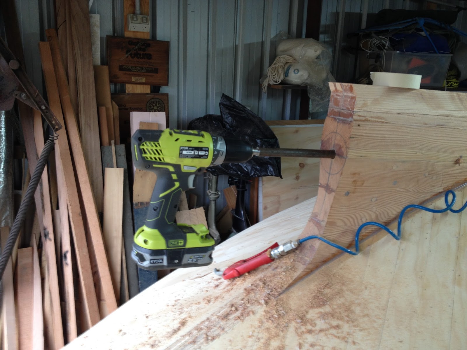
With that done I set about drilling the hole through the hull using the pilot hole in the skeg. I made up a drill extender from a piece of 16mm steel rod; turned one end down to 12mm to fit in the drill chuck and bored the other out to 1/2" for the big twist drills. The drill is held into the extension with Loctite. I started with an 11/16" drill bit to get some clearance for the extension. It looks like a test to destruction for a battery drill but it did the job without any drama (as the drills get bigger I may have to find a more powerful drill).
That's it, all done. I had to keep pulling the drill out to clear the chips and the air gun helped with that.
Now that I can see where the hole comes out on the inside of the boat ( about 2 or 3 mm off the centre line) I will make up and fit a block to support the inboard end of the stern tube. When this block is glued in place I will extend this initial hole through it and then set about making the hole bigger. I will do this with twist drills up to 1" and then rig up a boring bar exactly on the centre line to take the hole out to suit the 1.75" diameter stern tube.
With this much of the hull "finished" I continued work on the skeg and keel. This is tricky because the exact line that the keel fits to is not visible until the planking is finished and then planed back to a flat 75mm wide for the keel to sit on. That said, I had enough hull to prepare the landing for the skeg. The next photo shows the skeg balanced on the hull (which still comes to a point in the centre) as I try to convince myself that it will all work out right in the end. There's a string line down the centre of the boat and the stick poking out of the pilot hole in the skeg is on the line of the stern tube.
Here's the skeg sitting on the hull on the flat the I have planed from the stern as far forward as the 3rd layer of planking. I have added another lamination to the skeg; I hope that when all the planking is done the keel will sit on the skeg and follow the correct line along the hull.
I have glued the skeg in place with some 316 SS coach screws to add to the strength of the joint. I have great faith in epoxy but needed some screws to hold the skeg in place until the glue set so used some substantial screws.
With that done I set about drilling the hole through the hull using the pilot hole in the skeg. I made up a drill extender from a piece of 16mm steel rod; turned one end down to 12mm to fit in the drill chuck and bored the other out to 1/2" for the big twist drills. The drill is held into the extension with Loctite. I started with an 11/16" drill bit to get some clearance for the extension. It looks like a test to destruction for a battery drill but it did the job without any drama (as the drills get bigger I may have to find a more powerful drill).
That's it, all done. I had to keep pulling the drill out to clear the chips and the air gun helped with that.
Now that I can see where the hole comes out on the inside of the boat ( about 2 or 3 mm off the centre line) I will make up and fit a block to support the inboard end of the stern tube. When this block is glued in place I will extend this initial hole through it and then set about making the hole bigger. I will do this with twist drills up to 1" and then rig up a boring bar exactly on the centre line to take the hole out to suit the 1.75" diameter stern tube.
Subscribe to:
Posts (Atom)