This blog describes in words and pictures the building of a Paul Gartside designed fantail launch. There are a number of fantail launches of various sizes on the Paul Gartside website at http://store.gartsideboats.com/collections/steam-launches.

My boat will look like his 20 foot steam launch but will be 18 feet long and will be powered by a small diesel or petrol engine or possibly an electric motor. I have built a rowing boat, one and a half sailing boats and a small canoe and so this will be something different.

If you would like to contact me please click to send me an email.

Wednesday, 27 April 2016

Strip Planking on Port Side

Since the last post (is it really 3 weeks ago?) I have slowly been fitting strips in the final layer on the port side. Here are a couple of photos; first shows progress after the first 2 days - 4 strips one day 6 the next. The strips are 50mm wide, the boat is 5.5 metres long so there are a lot of strips!


The last few strips were fitted yesterday, as you can see they get shorter and shorter. This didn't make them easier to fit because there is a "hollow" curve towards the stem and holding these last strips became quite tricky. The plastic nails I have been using didn't have enough grip so I resorted to "sky-props" and screws through pads.

So, that's one side finished. The other side of the boat will take at least a couple of weeks and I will post something when I get there.

Wednesday, 6 April 2016

Stern Tube Hole

Work on this was mentioned in an earlier post. At that time there was a pilot hole all the way through the skeg and keel. Over a period of days I have slowly fitted the block to the inside of the keel and extended the hole through it. A selection of twist drills on the end of a long extension took this hole out to 32mm. At the end of this the hole was about 5mm off the centreline inside the boat. A boring bar was used to open up the hole to about 46mm for the stern tube.

Bearing blocks were set up at both ends of the hole to carry the boring bar that would finish the job. At the outer end I made up an aluminum bush to be a good fit in the pilot hole and to the boring bar. Here's a photo of the bar in place and the timbers that will support the bearing block.


At the inside end the pilot hole didn't allow the boring bar to be centered. This photo shows the 32mm pilot hole with the lines showing where the final hole should be. The bearing block with its 25mm hole was screwed to the support as far to the left as the pilot hole would allow. When the hole was large enough to allow the boring bar to be moved over the bar and inner bearing were removed and the pilot hole in this supporting timber made larger. Then the bearing block was reattached with the bar lined up accurately on the centreline. The final arrangement of this inner bearing is shown clearly in the last photo below.


Now the boring bar is supported at both ends the cutting can begin. One photo was taken when the hole was close to the final diameter and it shows the cutter clearly. The hole was opened out in steps from 32 to 46mm, each step removed about 1mm of timber. After the first few steps the inner bearing was moved to the centreline. The other photo shows the battery drill that turned the bar - fortunately I have 3 batteries for this drill but there were still pauses while batteries were recharged. Very cruel to the drill but it survived!


There was a problem about halfway through the hole where it passed through the 3 layers of plywood. The cutting tool handled the oregon in the skeg and the block inside the hull but had trouble with the glue lines and interlocking grain in the plywood. The is resulted in a hole that was a couple of millimetres smaller in this middle section. Advice from a friend led me to reshape the cutting edge of the tool and then to hone it to a very sharp edge. This solved the problem and there is now a nice parallel hole ready for the stern tube.


The hole is about 780mm long and nicely centred at both ends. I will leave the bearings for the boring bar until the stern tube is fitted using the boring bar to line it up while it is glued in place.

Shingles

Not the shingles you put on the roof but the disease. Here's the short story, may not be medically accurate but it's close enough for a boat builder! In earlier days you had chicken pox. The virus that caused it is still in your body. Later on it breaks out (reasons uncertain, but stress or being run down are high on the list) and causes shingles. Shingles causes a rash and a certain amount of pain and suffering. If you get to your GP quickly enough (within 48 hours) there is a drug which helps your immune system to get the virus under control. If you are one of the lucky ones the problem will resolve itself in 2 or 3 weeks. If you are unlucky it might be months or years. I'm now at the 2 month mark and still have a lot of pain from the nerves that were affected by the virus. I am now going to try to continue business as usual, as much as the pain will allow. Boat building will resume and blog posts will continue but progress may be slower than I would like!

Saturday, 20 February 2016

I Have Plywood, BUT........

The ply wood finally came off the production line.


Don't worry about the rust bucket of a trailer; the wheel bearings are OK and the lights work. Good quality rust holds it all together!

Interesting how the plywood is packed: there are 4 large pieces of 12mm thick coated particle board that will eventually be put to good use (frames for the next boat maybe - arghhh, did I actually say that), a large sheet of white plastic (useful when painting) and a 2.2x1.2m sheet of cardboard (for making patterns). All this extra looks like useful "free" stuff but I guess I'm paying for it, sigh.

The BUT in the title of this post is because I have shingles! Any form of exertion is out of the question so, again or still, boat building is not on my agenda.


Saturday, 13 February 2016

Still Waiting for More Plywood

I'm still waiting for plywood; the latest suggestion is that it will be towards the end of next week! I used up the remaining ply starting behind the mid section and working toward the stern. I have used 50mm wide strips on this final layer and the result is tidier although there will be a lot more nail holes to fill! Here's a photo of the stern. The apparent kink in the sheer will disappear when the corner is planed off to make a land for the gunwale.


With this much of the hull "finished" I continued work on the skeg and keel. This is tricky because the exact line that the keel fits to is not visible until the planking is finished and then planed back to a flat 75mm wide for the keel to sit on. That said, I had enough hull to prepare the landing for the skeg. The next photo shows the skeg balanced on the hull (which still comes to a point in the centre) as I try to convince myself that it will all work out right in the end. There's a string line down the centre of the boat and the stick poking out of the pilot hole in the skeg is on the line of the stern tube.


Here's the skeg sitting on the hull on the flat the I have planed from the stern as far forward as the 3rd layer of planking. I have added another lamination to the skeg; I hope that when all the planking is done the keel will sit on the skeg  and follow the correct line along the hull. 


I have glued the skeg in place with some 316 SS coach screws to add to the strength of the joint. I have great faith in epoxy but needed some screws to hold the skeg in place until the glue set so used some substantial screws.

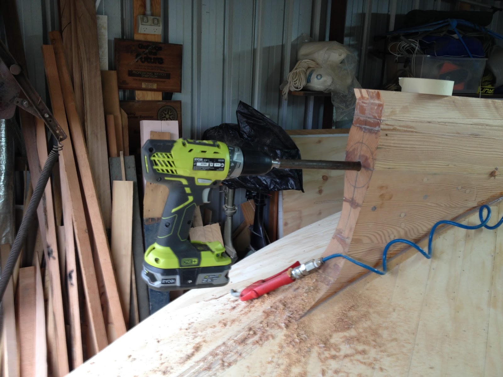
With that done I set about drilling the hole through the hull using the pilot hole in the skeg. I made up a drill extender from a piece of 16mm steel rod; turned one end down to 12mm to fit in the drill chuck and bored the other out to 1/2" for the big twist drills. The drill is held into the extension with Loctite. I started with an 11/16" drill bit to get some clearance for the extension. It looks like a test to destruction for a battery drill but it did the job without any drama (as the drills get bigger I may have to find a more powerful drill).


That's it, all done. I had to keep pulling the drill out to clear the chips and the air gun helped with that.


Now that I can see where the hole comes out on the inside of the boat ( about 2 or 3 mm off the centre line) I will make up and fit a block to support the inboard end of the stern tube. When this block is glued in place I will extend this initial hole through it and then set about making the hole bigger. I will do this with twist drills up to 1" and then rig up a boring bar exactly on the centre line to take the hole out to suit the 1.75" diameter stern tube.


Tuesday, 26 January 2016

Waiting For More Plywood

I'm still waiting to hear about the next batch of 5mm plywood; the mill suggested February 4th as a possibility but I'm not holding my breath. In the meantime I set about making the outer part of the stem.

This outer stem is 75mm wide and 80mm thick at the maximum point but it tapers towards the sheer. I decided to laminate it out of 10 x 8mm thick strips but these would be difficult to bend and would probably break. So I built a steam box and read about steam bending timber. It sounds straightforward and making the steam box was. Using it was easy too, just put the wood in and cook it at 100C for an hour per inch of thickness. I expected that the wood would bend fairly easily while it was hot but...... Here's what I found out:

  • The timber cools and stiffens up very quickly so you have to bend it and clamp it in a matter of seconds,
  • The outside of the bend must be supported by a flexible strap to help prevent the fibres breaking away where the grain runs out.
  • A strong fixed former is needed to withstand the force involved. It has to be fixed so it doesn't move about when you heave on it.
  • It is difficult to do single handed, holding the bend in place and putting clamps in place needs 3 (or more) hands.
  • Each laminate would have to be bent individually because 2 or more would need more force to bend than one person (ie me) could apply. This would be tedious and would take several days.

Here's a photo of some of my test pieces; there were quite a few more!


I think my problems were: the test pieces were all too dry because it gets very hot in the shed (up to 40C), they were not carefully selected (the grain should be straight with no run outs where it has to bend), they might have been too thick (about 10mm), maybe they were not a good choice of timber.

Having spent about 3 days learning about steam bending I decided to Build up the outer skeg from solid pieces glued together in 4 layers. This is the same method that I used for the inside part of the stem. It is quick and easy. Here is the finished result which only took a couple of days to make. There are 4 layers of 19mm thick timber each made up of 3 pieces. The joints in each layer are staggered so that each joint lies against 3 layers without a joint. The gap between the hull and the stem at the upper left is the hooked scarf joint where the stem joins the keel. There is more work to do after the hull is finished and before the stem is glued in place.


I started building up the skeg but before I could do that I needed to know the size of the hole for the stern tube and to decide on that I needed to know the diameter of the propeller shaft and that depends on the propeller, etc, etc. This brought me to a standstill because there are too many variables. I muddled around for a while trying to work out what was needed. Eventually I managed to contact and meet a marine engineer (that took several days because it's a) holiday time and b) he was then working elsewhere on a boat) who cleared up all these issues in a few minutes. He said: use an off the shelf fibre glass tube because it is cheaper than buying the materials to make your own and is probably better quality, use an off the shelf "cutless" or "cutlass" bearing which is made to fit the tube, use a 1" diameter propeller shaft because the vast majority of propellers in the sizes I am interested in have a 1" taper bore (a smaller shaft would be strong enough but ground round 316 stainless steel smaller than 1" has to be made to order and is therefore very expensive).

So the outside diameter of the tube is 1.75" but he suggests making the hole a bit bigger to allow some wiggle room to get the tube and propeller shaft correctly aligned. Once the tube is lined up the space around it in the hole is filled up with epoxy "bog".

Here is the start of my built up skeg. There are 2 pieces at the moment, above and below the hole for the tube, The skeg is almost 100mm thick where the tube goes through and 75mm thick above and below that. I made it in 2 halves so that I could rout out a channel about 12mm square exactly along the middle of the join. I also routed out 2 grooves towards the edges of the join for splines to be inserted to locate the joint. Then I clamped the 2 halves together and ran a 16mm diameter drill through the hole.


You can see that the skeg has to be built up more to reach the bottom of the keel that will run the length of the hull. Once that is done I will glued the joint around the hole. Believe it or not but I ran out of timber the day before the Australia Day long weekend!

When the hull it complete the skeg and keel will be fitted in place and the 16mm hole used as a pilot hole to drill the rest of the way through the hull. Then a block has to be fitted inside the keel where the stern tube comes through and this will be glued in place when its location is known. The 16mm hole will be extended through this block. Finally the pilot hole will be opened up in stages using long drills and a boring bar until it is big enough (almost 2") for the stern tube. I have a selection of drills up to 1" and will make up an extension to work through what will be a hole almost a metre long. From 1" up I will make up a boring bar with an adjustable cutter because drills over 1" are expensive and of limited future use.


Monday, 11 January 2016

Second Layer Complete

Put the last of the strips in the second (middle) layer this morning. Traditionally this 3 layer cold molding has the diagonal strips in the first 2 layers and the outside (3rd) layer is longitudinal. This is because it looks better in a clear finished boat. I'm no longer sure why I chose to put the middle layer longitudinally but I am glad that I did because it is much easier to get a tidy pattern with the diagonal strips. Also, they are shorter and easier to handle.

The first side of longitudinal strips was a learning exercise; it doesn't look very tidy! The second side is better but still not very good. The appearance is irrelevant of course because it will be covered by the next layer and I know that this will look OK. Even there the appearance is only important to me because it, it turn, will be covered by one or two layers of fibre glass cloth and many layers of paint!

The thing about longitudinal strips is that the shape to be covered is maybe twice as wide in the middle as it is at the ends so the strips need to be tapered for it to look pretty. This leads to a lot of waste material and is perhaps why the recipes for calculating the material needed add a 25% allowance for wastage. Here is a picture of most of the "waste" material after my 2 layers are complete.


As you can see there are not many usable pieces there. The third diagonal layer will have a larger wastage because I will only use complete strips without any butt joints.

Here's a photo of the stern where you can see the different patterns as the strips run out. The starboard (left hand because it is upside down) is tidier but...... There are strips tapering out along the keel (at both ends) and along the "great circle" but the strips along the sheer are neater and don't have as much twist in them.


For all the boats I have built I have used plastic drink glasses to mix epoxy because they are cheap, maybe 10c each depending where you shop, and I use them once and toss the in the bin. I have used 100s of them, maybe even a few thousand, and never though twice about it. With this cold moulding I was using them at a much greater rate and made a discovery. If you let the epoxy go off overnight it is easy to remove and the cup can be recycled. Let the epoxy harden, squeeze the cup and put out the epoxy leaving a clean cup. Here they are with epoxy in them.


And here they are ready to go round again. I am getting about 5 or 6 uses before the plastic splits and they have to be binned. Just think of the money I am saving by building this boat!


Next steps are to scrape off the excess epoxy and sand the whole hull. I started the scraping this afternoon but my hot air gun gave out a big flash and became a cold air gun. Hmmm, I wonder if it is still under warranty?

I also need more plywood and can't get this until the mill goes back to work and makes some more 5mm ply. They are still on an extended Christmas holiday so there is going to be an extended delay.